 by
by 
TABLE OF CONTENTS
MSI’s EZ debug LEDs might seem like a trivial feature when purchasing a new motherboard, but it can save you hours when troubleshooting in case something does go wrong.
Few things can be more frustrating than building a new computer only to see nothing happen on your screen.
That’s when those humble debug LEDs will help you identify and fix the issue, and hopefully get your new build operational.
In this article, we’ll go over the most common issues encountered when building a new PC and how EZ debug indicators of an MSI motherboard can help you find and fix those issues.
What Are EZ Debug LEDs Good For?
Pressing the power-on button and turning on a PC for the first time after building it can be quite stressful. At times, this action will do — well, nothing.
Even after carefully assembling all the components, there’s a myriad of minor mistakes that can be made, and pinpointing which one is obstructing the system’s initiation process is no easy task.
This is where EZ Debug LEDs come in handy. They light up and show you what component is running into an issue.
Instead of going through each individual component to investigate the possibility of an installation error, you can check your components according to the illuminated LED indicator.
To check if your motherboard is equipped with EZ Debug LEDs, download your model’s manufacturer manual, or check the (usually) upper-right-hand corner of your motherboard near the RAM slots.
You can find your motherboard’s manual online by searching through MSI’s database.
Another way to find out would be to head to your motherboard’s product page on MSI’s website. Navigate to the ‘Specifications’ page using the top menu there and then click the ‘Detail’ tab on the specifications page. Here, use Ctrl + F to find the term ‘EZ’ (without the quotes). If your motherboard does support the feature, ‘EZ Debug LED’ will be listed under the LED Feature section of the detailed specifications.
How to Read MSI EZ Debug LEDs
The very first thing to catch your attention when your PC fails to boot or POST, should come in the form of a question like: “What is that glaring red light emanating from the motherboard? That doesn’t bode well..”
Let the EZ Debug LED Settle
The LED may or may not be color-coded, depending on the motherboard model.
Sometimes the CPU error may be red; other times, it may be white. When any of these debug lights appear, they will remain solid until the issue is fixed.
The debug LEDs may blink during the boot process, but this is normal. It only becomes an issue when the light becomes fixed on a particular LED, so you want to give it enough time to settle on the problematic component. (Give it a few minutes, especially when doing your first boot)
It is only natural to be concerned, as this light may translate to a plethora of different issues. These can range from benign to innate hardware defects that will require a replacement.
And, because we all dread going through the process of a replacement, it’s best to eliminate all other external factors that may be the cause before starting time-consuming RMA processes.
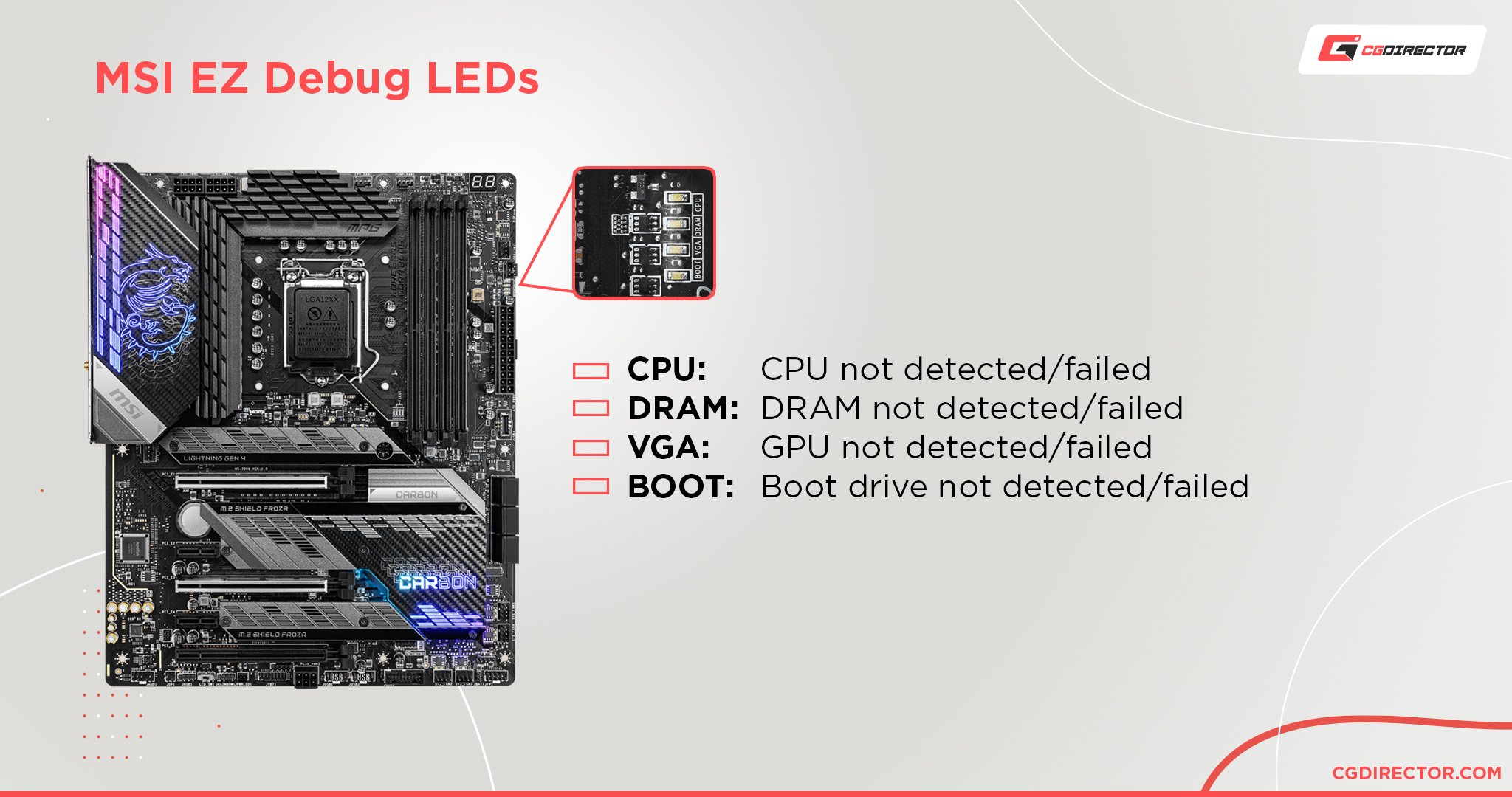
List of LEDs
The LEDs on the motherboard appear in the following order from top to bottom — You may also find these labels written directly on the Motherboard:
- CPU
- DRAM
- VGA
- BOOT
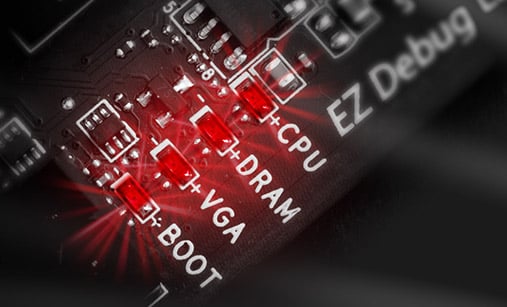
Close-up of the MSI EZ Debug LEDs on the Motherboard. Image-Credit: MSI
How to Troubleshoot and Fix EZ Debug LEDs
Now that we know what each EZ debug LED represents, let’s investigate how to fix the issue they indicate.
Though this may seem obvious, you first want to check if your motherboard supports the components you are trying to install.
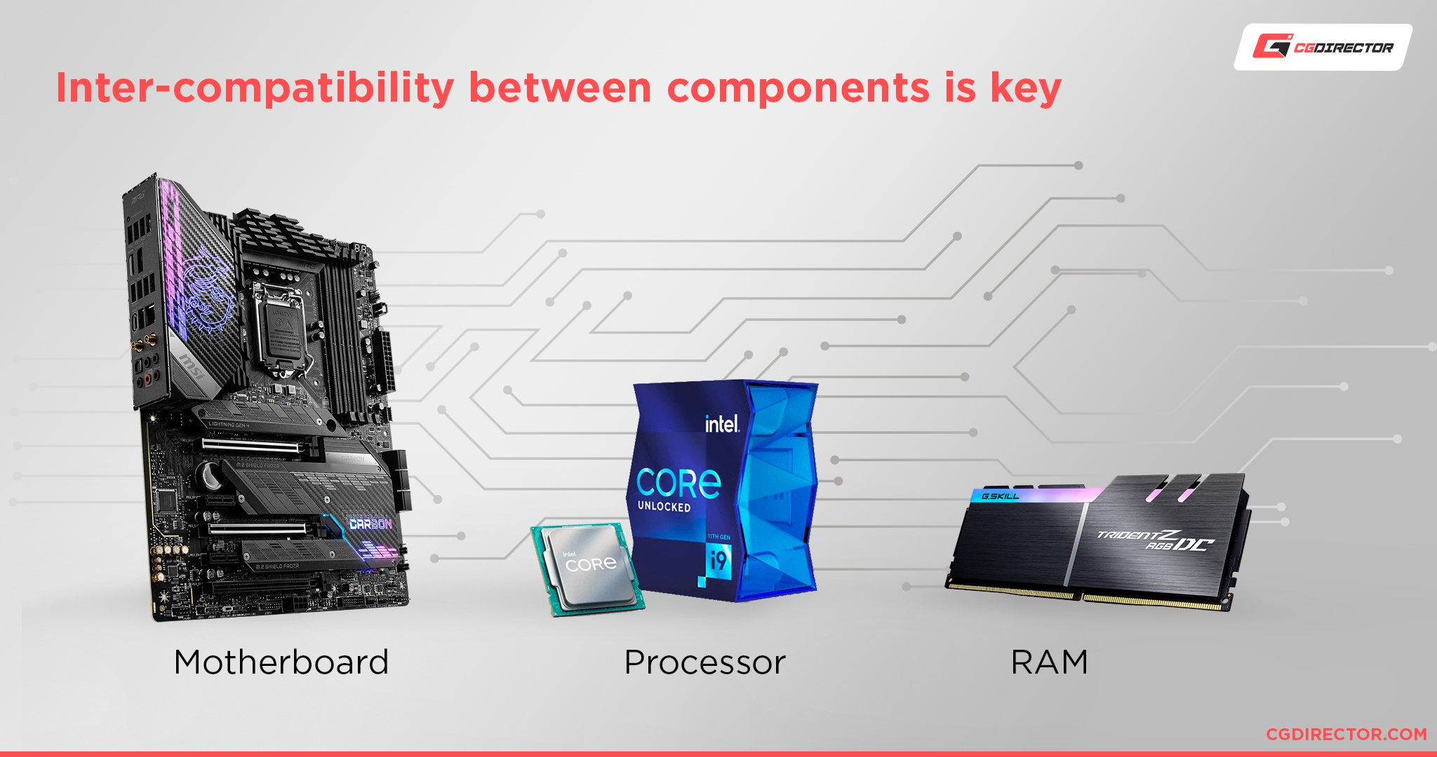
To do so, go to MSI’s webpage, and click “Support” on the top right-hand. There, you will see a list of all compatible components (CPU, GPU, storage) that are supported. On the support page, you’ll also see supported RAM kits for your motherboard. This is called a QVL (Qualified Vendor List) and is covered in this memory buying guide.
Planning your PC meticulously is a crucial step in ensuring that your components are compatible with one another and that they work harmoniously to maximize their performance.
CPU
CPU Power Connector
The first thing you want to check is if the 4-pin or 8-pin CPU power connector is properly installed.
Note that you can plug a 4-pin power connector into an 8-pin power socket, and the CPU will still function in most cases, though for limited use. (No OC, etc.)
Check the Pins and Socket for Obstructions
The next step is to remove the CPU to check it for any potential damage, dirt, or thermal paste that may be blocking its connection to the socket. If any such stain is present, clean it and reinstall the CPU.
Bent or Broken Pins
If the CPU and CPU socket are clean, check to see if there are any bent or broken pins. Bent pins are fixable and can be straightened using a razor blade or a needle.
If a pin is broken, the CPU may still work. This is entirely dependent on which pin is the culprit. For example, a Ryzen AM4 CPU pin map shows the areas in which there are certain VSS and test/debug pins that are non-essential.
If these were to break off, the CPU would still have the potential to operate normally. However, if the pins are bent, an error will occur.
Hence why it is always best to check and see if you can fix any bent pins to the best of your ability before proceeding with a replacement.
Compatibility
Although the CPU might fit into the socket, the Motherboard and its BIOS have to support it as well.
Check the Motherboard’s QVL (Qualified Vendor List) to see if it supports the CPU you are trying to use or if you might have to update the BIOS to make it compatible.
DRAM
Before troubleshooting the DRAM, do note that many times bent CPU pins may also cause the DRAM EZ Debug LED to illuminate rather than the CPU debug LED.
Proper Installation into the Socket
One of the most common mistakes that may cause a PC to fail its Power-On-Self-Test is the improper installation of a RAM stick into its DIMM socket (also called a RAM slot).
First, remove the RAM module(s) and ensure that nothing obstructs the connector pins and sockets.
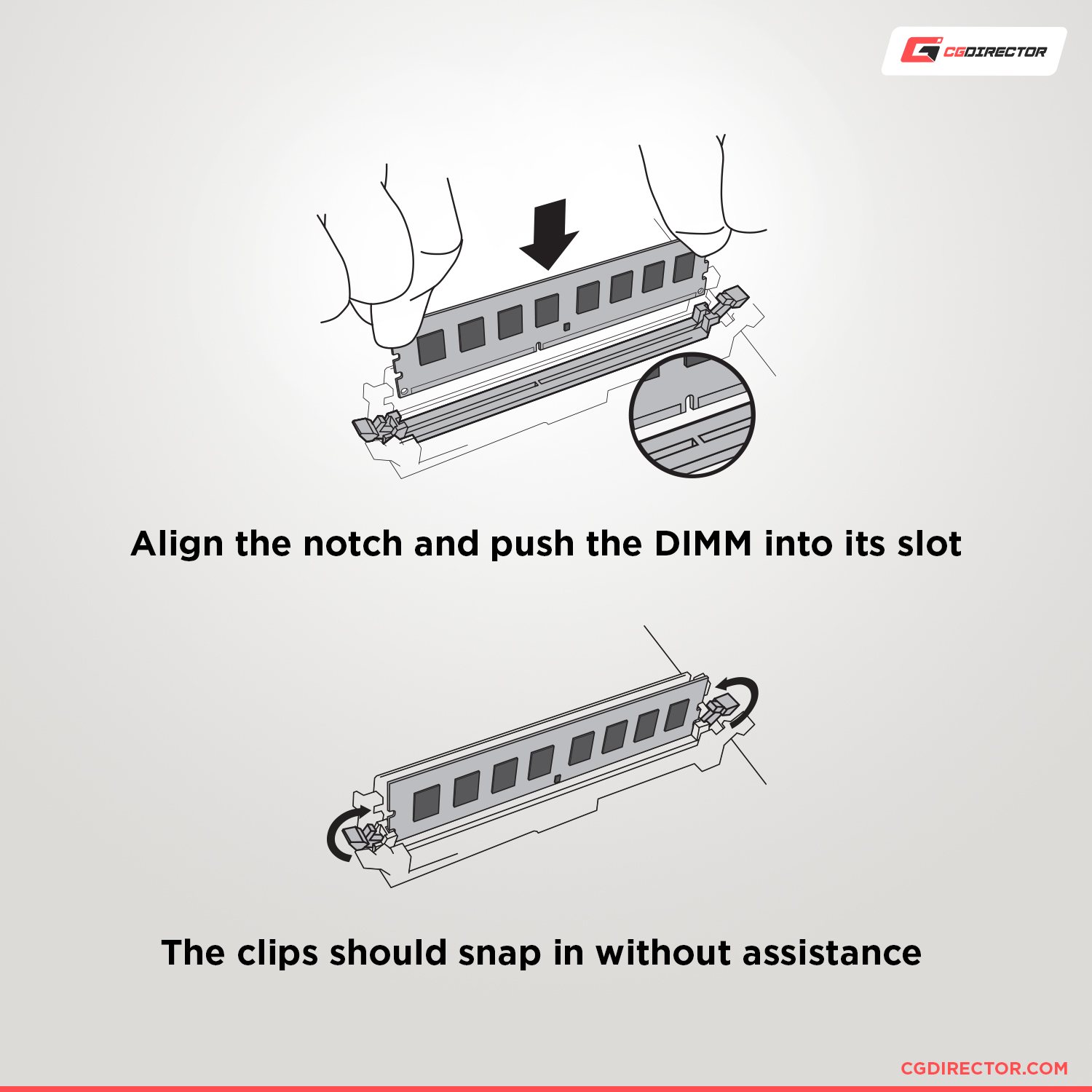
Next, install the DRAM stick into the second memory slot from the CPU (This may vary — consult your motherboard manual).
Making sure that the notch near the center of the module is aligned with the notch of the socket. Push down until you hear an (two) unmistakable click sound(s), and the safety tabs on both sides are properly secured into place.
Memory Configuration
If the RAM is properly installed and the DRAM debug LED is still lit, check to see if the RAM sticks are placed per your motherboard’s suggested configuration.
If using multiple RAM sticks, ensure none are installed in the wrong memory slot. You can also try removing all but one stick and attempt to reboot.
If that doesn’t work, try plugging in a different (single) memory stick, and try again via both the first and second memory slots.
Also, make sure the Motherboard supports the RAM Modules you bought. The QVL List on your Motherboard’s support page will let you know.
VGA
If the VGA light appears, then the issue should be pretty straightforward.
If your CPU has an integrated graphics processor, you will want to check the aforementioned troubleshooting steps for the CPU.
If you have a separate graphics card, you should ensure that it has been installed into the PCIe socket properly and the latch at the back of the socket clicked into place.
Try the topmost PCIe-Socket first (the one closest to the CPU), and try others if this does not work.
Of course, the 6-, 8-, or 12-pin power connector must also be plugged into the Graphics Card securely. As with all components, make sure that the pins of the GPU and the PCIe slot are clean prior to installation.
If you have a dedicated Graphics Card, your Monitor(s) must be plugged into the display connectors of your Graphics Card (not the Motherboard)! If you are using the iGPU of your CPU, plug the Monitor into the Motherboard’s Display connector (e.g. HDMI, DisplayPort).
BOOT
The boot EZ debug LED refers to the storage unit of your build. Depending on what type of storage drive you’re using, you will want to check if they are connected to the motherboard properly.
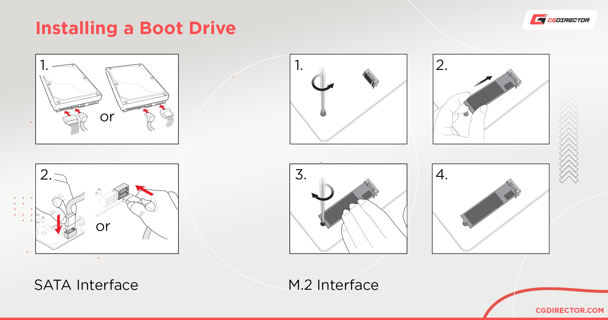
M.2 SSD
For M.2 SSDs, check to see that the pins are clean and properly inserted into their corresponding slot. Also, confirm that the screw has locked the SSD into place.
Note – Some motherboards (especially older ones) don’t support NVMe M.2 devices as boot drives. If you’re booting from an M.2 storage device, please consult your motherboard manual to confirm whether your board lists any limitations.
Also, make sure you give our M.2 Troubleshooting Guide a read.
SATA SSD/HDD
For storage drives connected via a SATA port, the first step you want to take is to remove the SATA cable from the motherboard and the storage unit and then re-plug it securely.
Also, try plugging it into a different port if that doesn’t work; and if you are still having issues, try replacing the cable.
If none of the above work, you may want to try an entirely new storage device.
Beware that some SATA Ports might be disabled, depending on the amount of PCIe Lanes other components are using. For example, if you are using two or more NVMe M.2 SSDs, it might very well be that some SATA ports are disabled (Usually Port 5 and 6). Consult your motherboard manual to see if this might be the case.
No Debug LEDs Lighting Up
Now, if you do not see any LEDs turn on when the PC fails to boot/POST, it may be an issue relating to the power supply unit you are using.
First, double-check that the 24-pin ATX power supply connector is properly plugged into the motherboard. If your motherboard has any RGB lights, check to see if they are illuminating.
Even when the power is off, power supplies continue to supply the motherboard with 5V of electricity, so LEDs will remain lit.
Also, check to see if the power plugs are properly connected and that the electrical socket supplies electricity.
Ensure your Power Supply Power Switch at the back of the PSU is set to “On”.
Other Issues
If none of the above help, there are still a couple of tricks you can try.
Firstly, you can try resetting the BIOS. Instructions on how to do so for an MSI motherboard can be found here. You will also find instructions on how to conduct a Power-On Self-Test (POST) on this page.
If you can get into the BIOS, you will want to update the BIOS and reset any overclock settings (especially for the DRAM) to their original values. Here is a link to MSI’s official BIOS manual.
What are Debug Numbers called “POST Codes”?
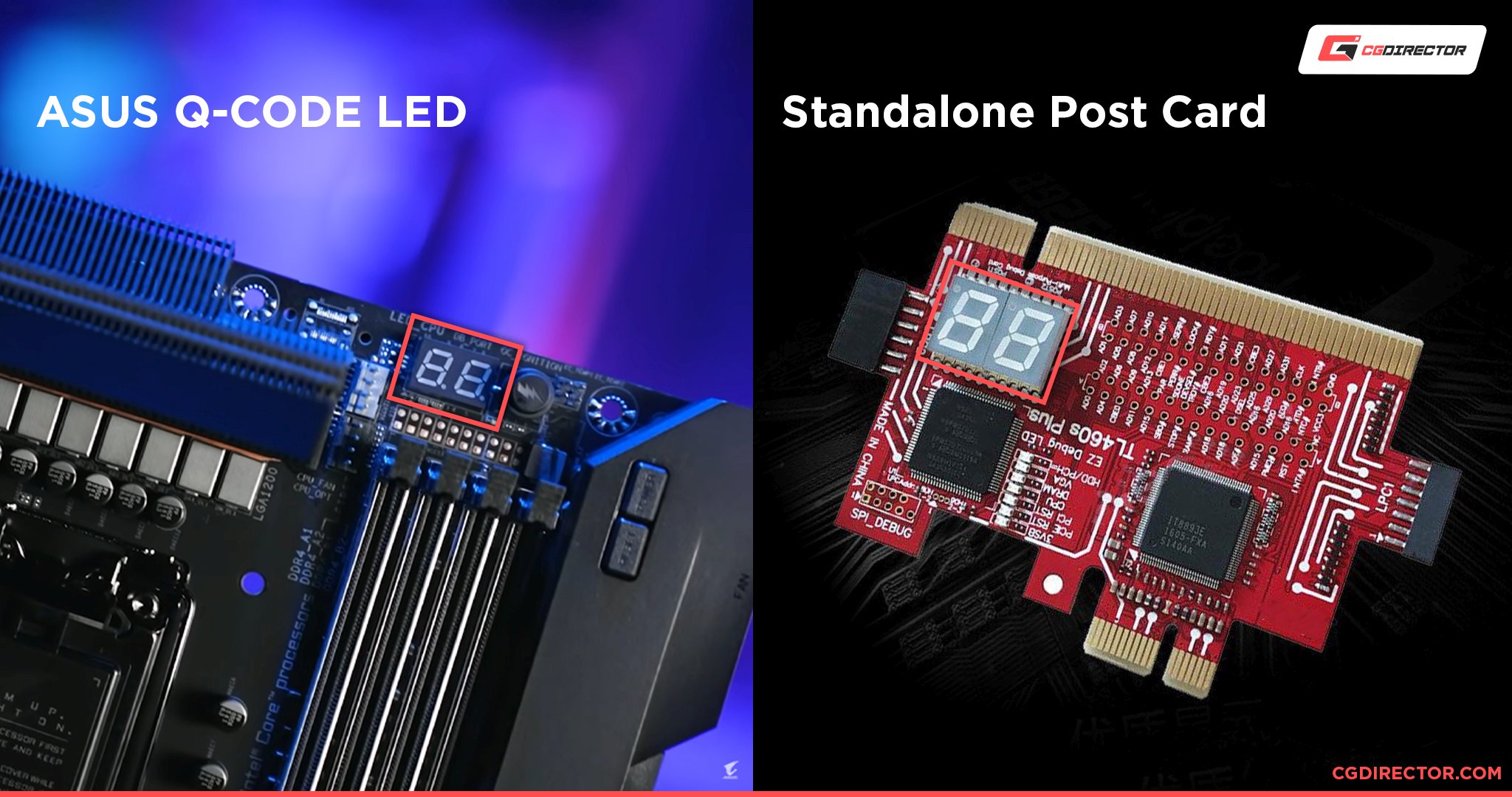
Certain motherboard models include what is called a POST code. You can also buy and install it as an add-in card using a PCIe slot.
This POST code can also be found in USB form, like the AMI Debug Rx.
Though a bit more complex than the troubleshooting steps above, these POSTcodes display numbers and characters that can provide a detailed diagnosis of what is inhibiting the startup process.
Here’s an overview of what these Codes mean on an MSI Motherboard.
How to Troubleshoot Through POST Codes
To attain POST Codes, you must at least have a working CPU, BIOS, and a working PCIe or USB slot for the POST card to run on.
Make sure to remove any peripherals; including any USB devices, flash drives, hard drives, etc.
The exception to this is the DRAM, which, if operational, can allow you to reach the BIOS screen on your monitor.
If you receive an error code on the POST card, you can find it in the corresponding tables of error messages and responses. Interpreting the code will allow you to find the exact error that is preventing your PC from booting properly.
If no error code is received, plug in the remaining peripherals and repeat the process until one is provided.
Conclusion
This article is meant to serve as a general guide for the most common issues found and associated with either building a new PC, or having an EZ debug LED appear for what used to be an operational PC build.
Of course, each setup will have its own idiosyncrasies, so errors can be unique and difficult to pinpoint when using generalized articles.
For such cases, it is best to post about your experience on either a subreddit – like/r/buildapc – or a specialized forum like MSI’s global English forum.
You can also use our very own expert forum, where you can connect with a host of other users and experts that can help you with the specific issue you are facing.
Another option is to leave us a comment on this article and let us know what troubleshooting issues you are facing with your build, as we are always happy to help.


")

5 Comments
1 June, 2023
thank you. great post.
my problem is that when booting for the first time, the cpu and dram lights come red nad go out, but then none of the other ez leds come on…and no image…
21 March, 2023
Hello wanted to add, that the DRAM LED is also lit, when you did not connect the power cable correctly to the PSU.
31 January, 2023
Thank you very much!!! That information helped me a por!!
29 July, 2022
cannot register 570 mb 601-7b93-050t11909000563
8 August, 2022
Hey Mark,
Where is this error shown? On the POST Screen? What kind of components do you have?
Cheers,
Alex